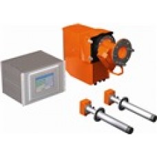
Measuring system for greenhouse gases Sick GHG-Control (GHG-Control)
| Gas Analyzers | |||||||||||||||||||||||||||||||||||||
| |||||||||||||||||||||||||||||||||||||
| Technical data | |||
| Measuring principle: | Gas filter correlation, Interference filter correlation, Ultrasonic propagation time delay measurement | ||
| Number of measuring components: | 3 | ||
| Measuring ranges: | CO2: 0 ... 22.5 Vol.-% / 0 ... 100 Vol.-% Gas velocity: -40 ... 0 m/s / 0 ... 40 m/s N2O: 0 ... 60 ppm / 0 ... 2,500 ppm | ||
| Measuring paths: | 2 ... 7.5 m | ||
| Process temperature: | 0 ... 180 °C | ||
| Process pressure: | depending on purge air supply | ||
| Process gas humidity: | 0 ... 100 % relative humidity | ||
| Dust load: | ≤-2 g/m3 depending on dust properties | ||
| Ambient temperature: | -40 ... 55 °C | ||
| Ambient humidity: | 0 ... 96 % relative humidity- bedewing of optical surfaces not permitted | ||
| Remark: | Measuring ranges depend on device type, Measuring ranges refer to 1 m measuring path | ||
| Electrical safety: | CE | ||
| Enclosure rating: | IP 65 | ||
| Analogue outputs: | 2 outputs: 0/4 ... 22 mA, 500 Ω- electrically isolated- max. number of outputs depends on application | ||
| Analogue inputs: | 2 inputs: 0/4 ... 22 mA, 100 Ω- electrically isolated- max. number of inputs depends on application | ||
| Digital outputs: | 5 outputs 2 power relays, electrically isolated- 3 outputs, floating- max. number of outputs depends on application | ||
| Digital inputs: | 4 inputs open contacts, floating- max. number of inputs depends on application | ||
| Interfaces: | Ethernet | ||
| Bus protocol: | Modbus TCP, OPC | ||
| Operation: | Menu-driven operation via SCU control unit | ||
| System components: | GM35 analyzer, FLSE100 sender/receiver units, SCU control unit | ||
| Test functions: | Automatic control cycle for zero and span point, Extended device diagnosis via SOPAS ET software | ||
| Note: | The scope of delivery depends on application and customer specifications. | ||
Написать отзыв о Measuring system for greenhouse gases Sick GHG-Control (GHG-..
Ваше Имя:Ваш отзыв:
Оценка: Плохо Хорошо
Введите код, указанный на картинке:


